Assembly Jamming Palm
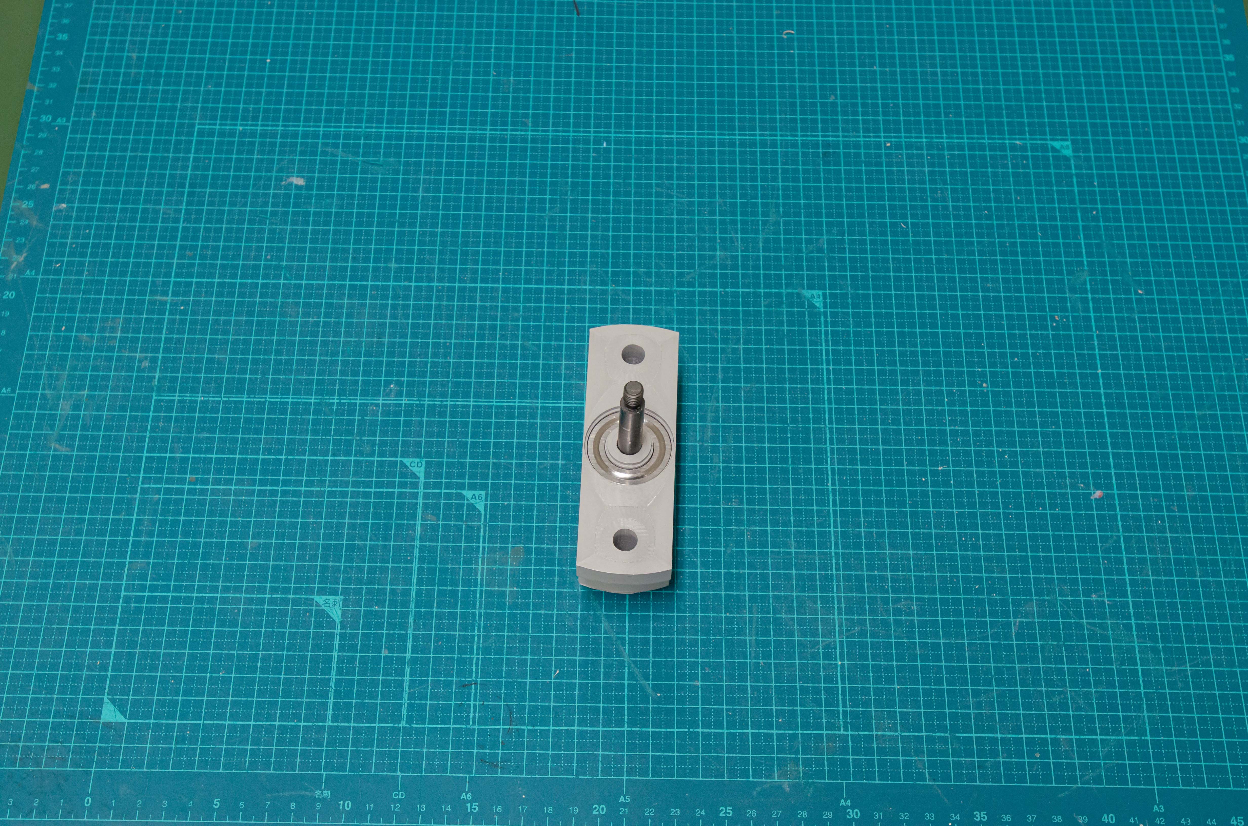
To assemble this component you will need the following items: cup, filter, jamming holder, inflatable ball, glass beads, and fitting.
Tools required: scissors, soldering iron, Phillips screwdriver, and hex wrench to fit the fitting.
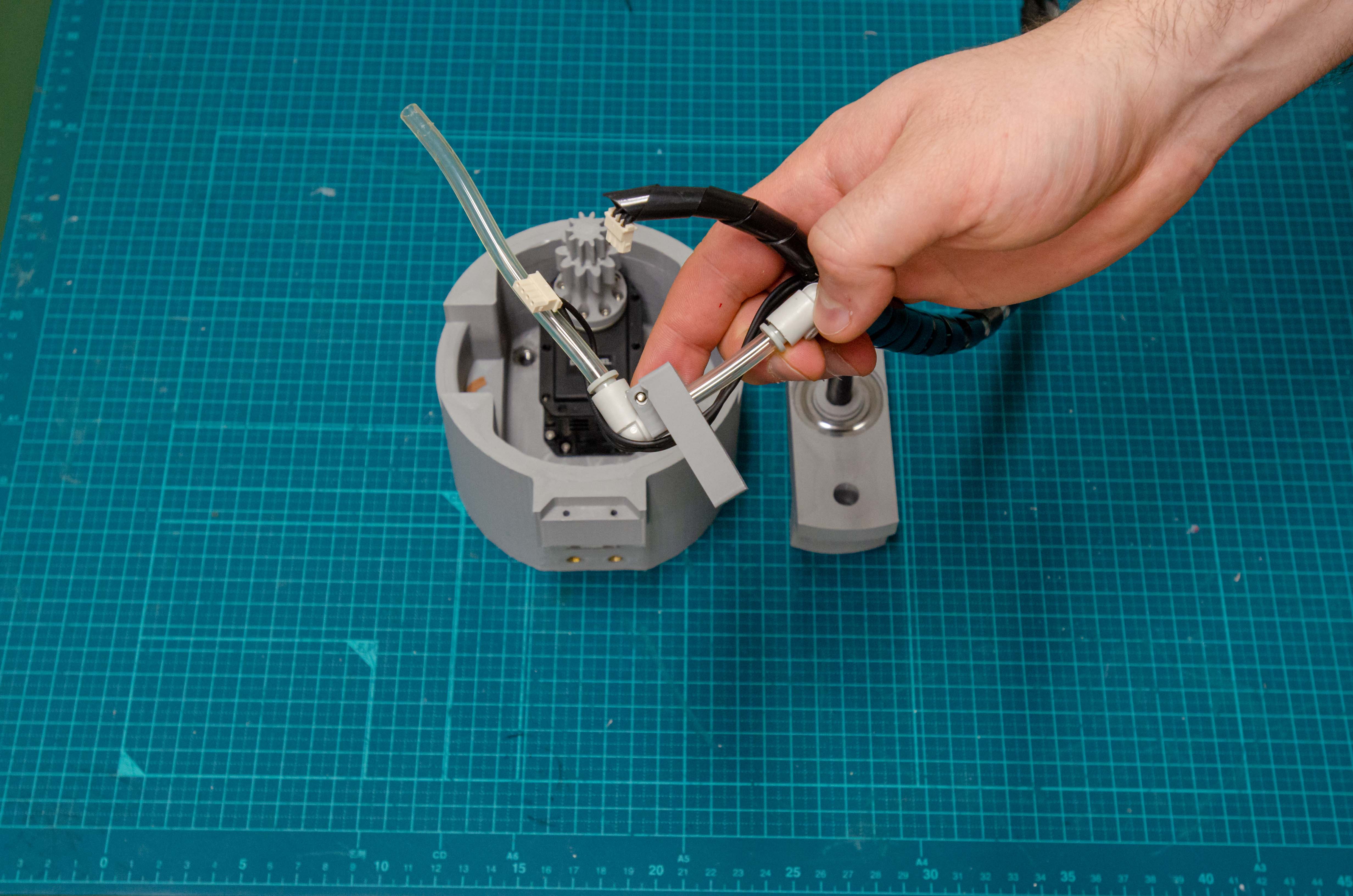
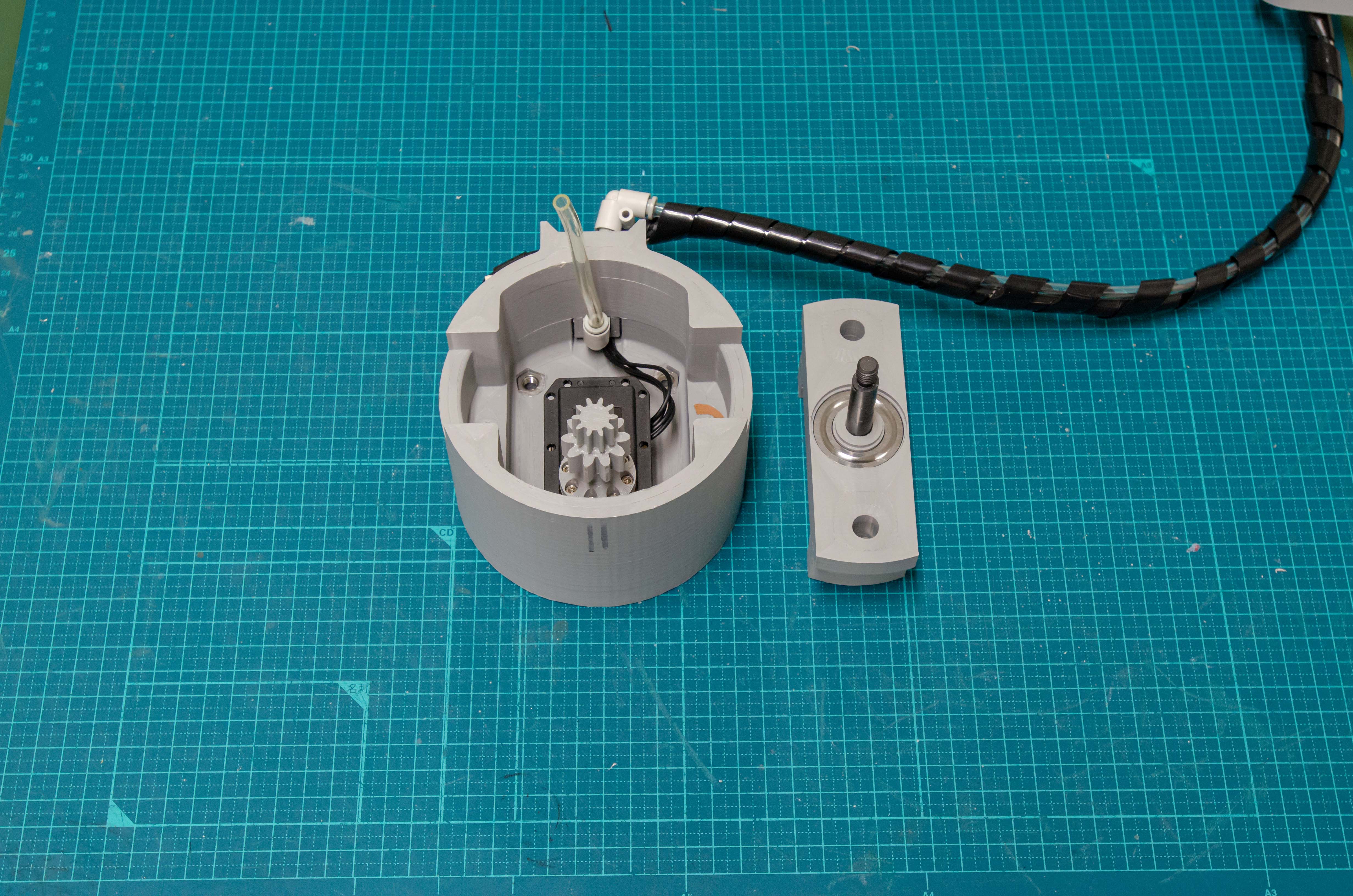
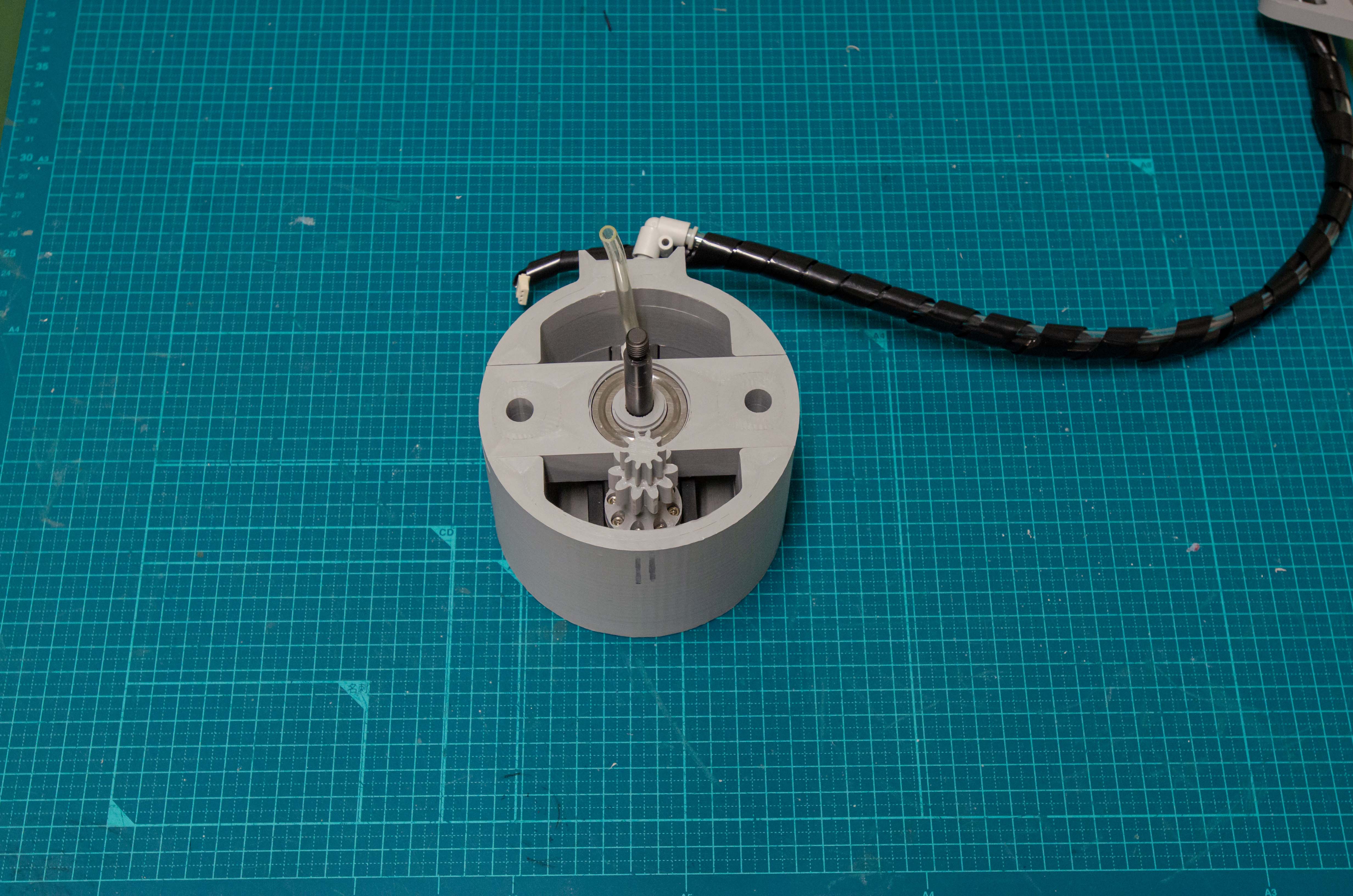
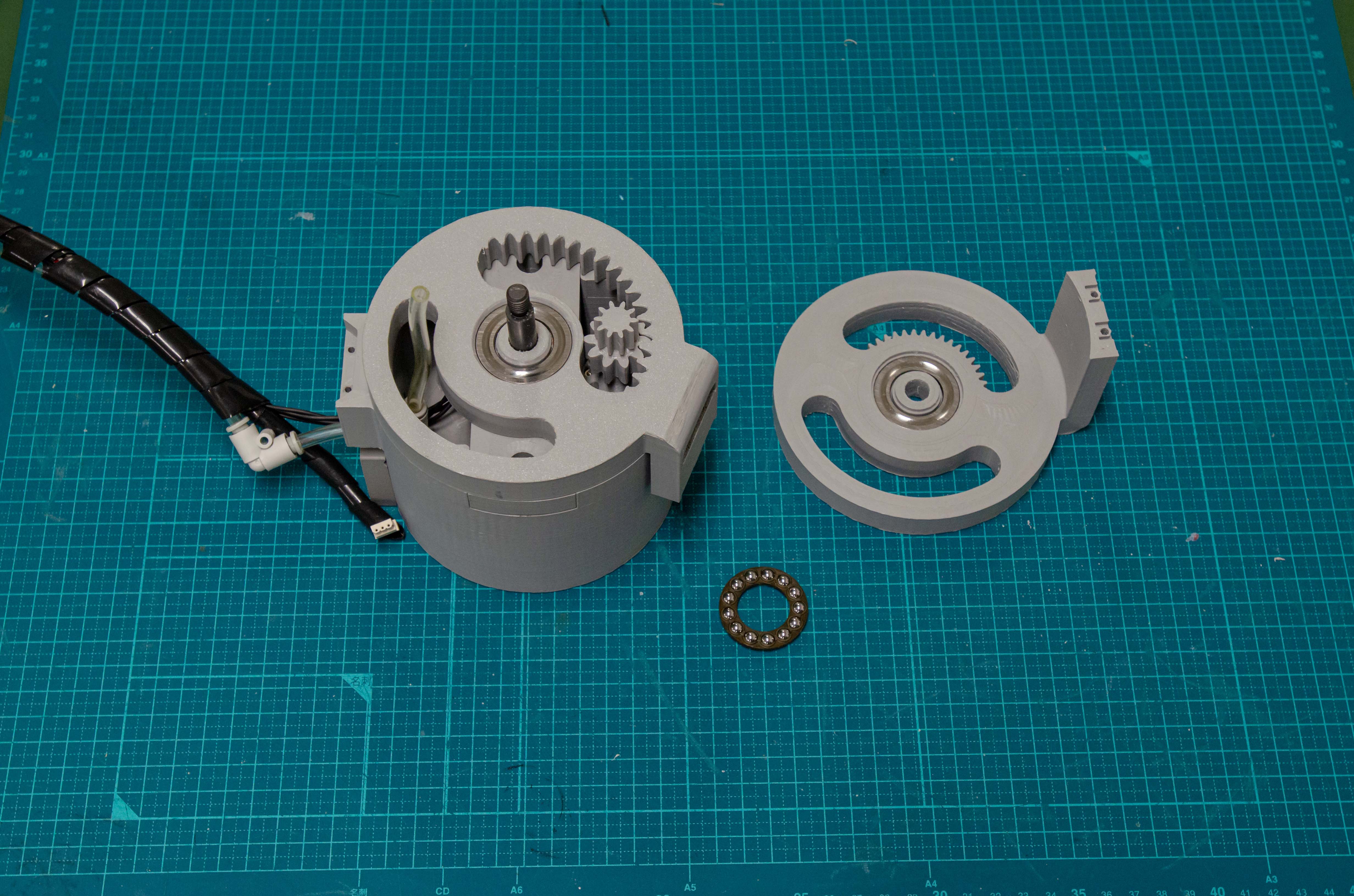
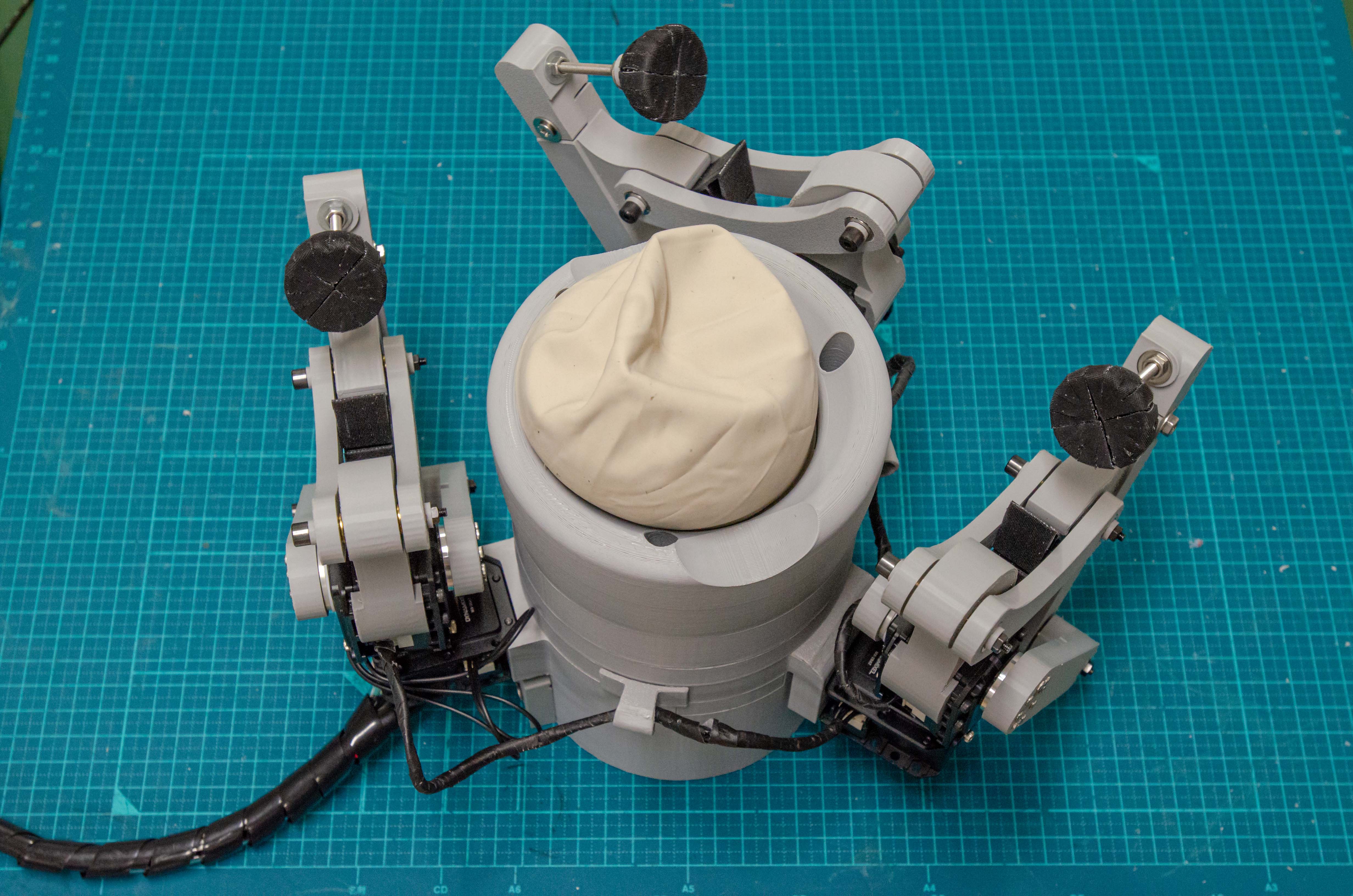
First, need to cut the neck off the ball (step 2), then insert the jamming holder into the middle of the ball (step 4), holding the ball on the edge, punch 6 holes for the connection (steps 6 and 7), pour glass bead into the ball (step 9), screw the jamming holder to the cup (step 10), and screw the fitting into the thread on the back of the cup (step 11).
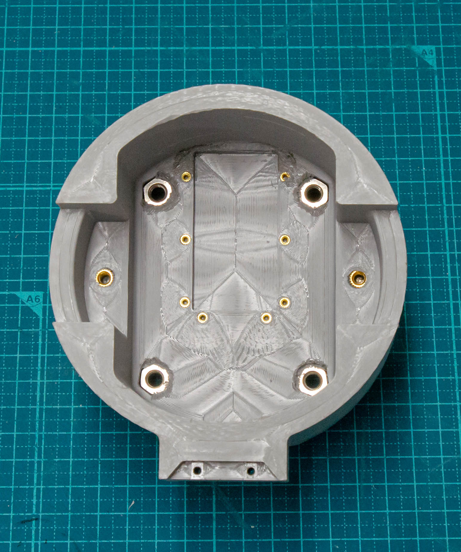
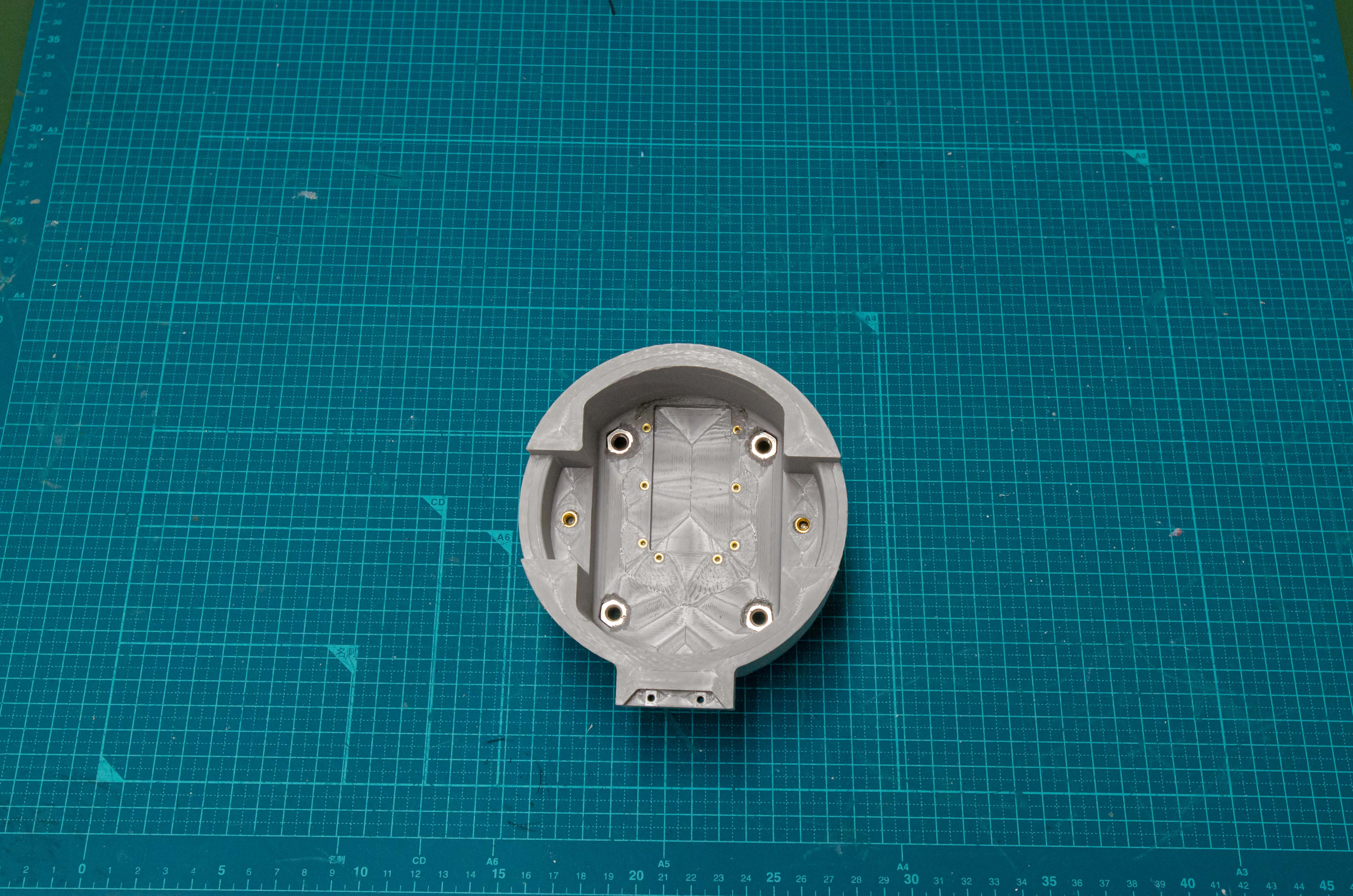
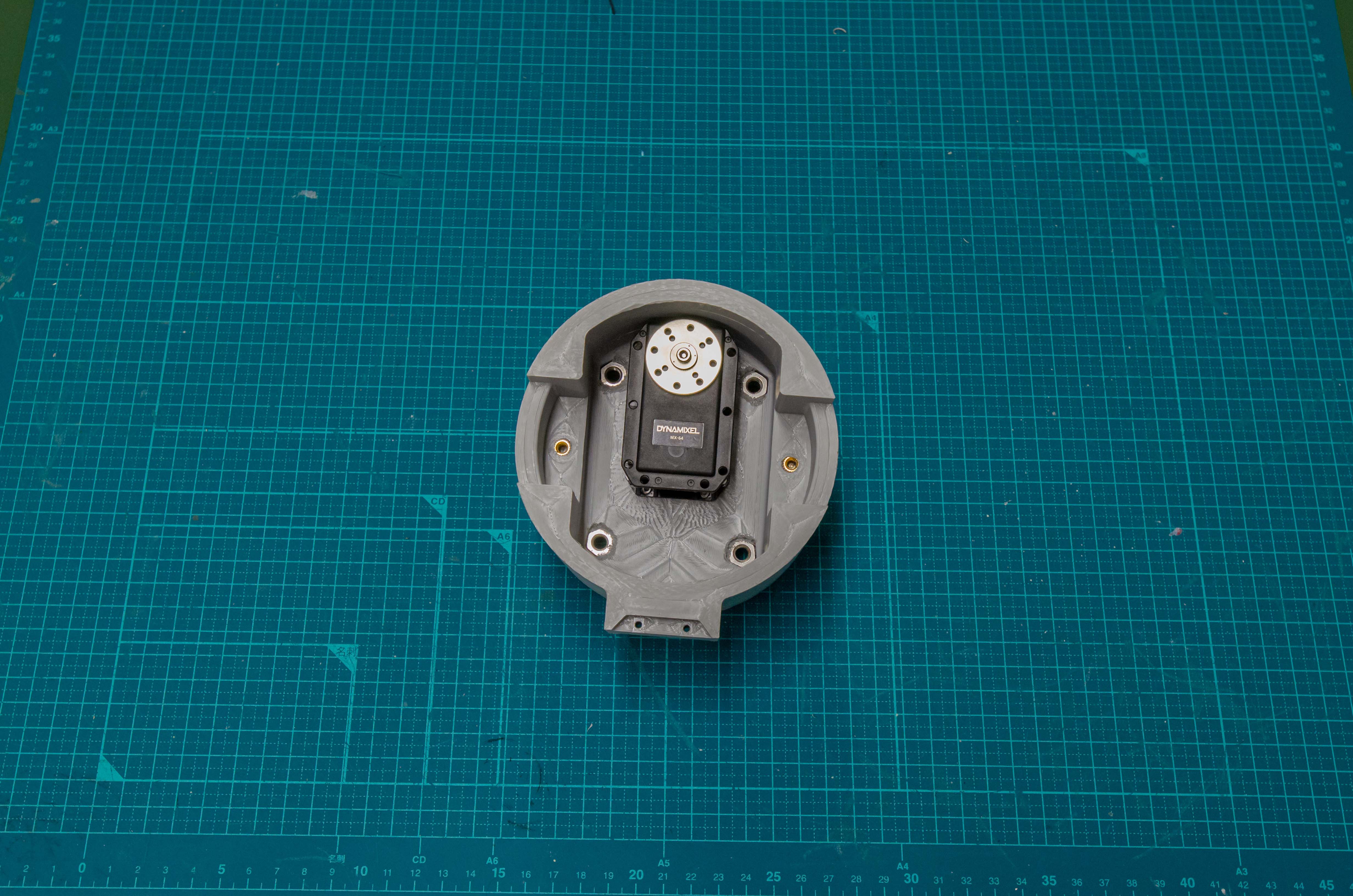
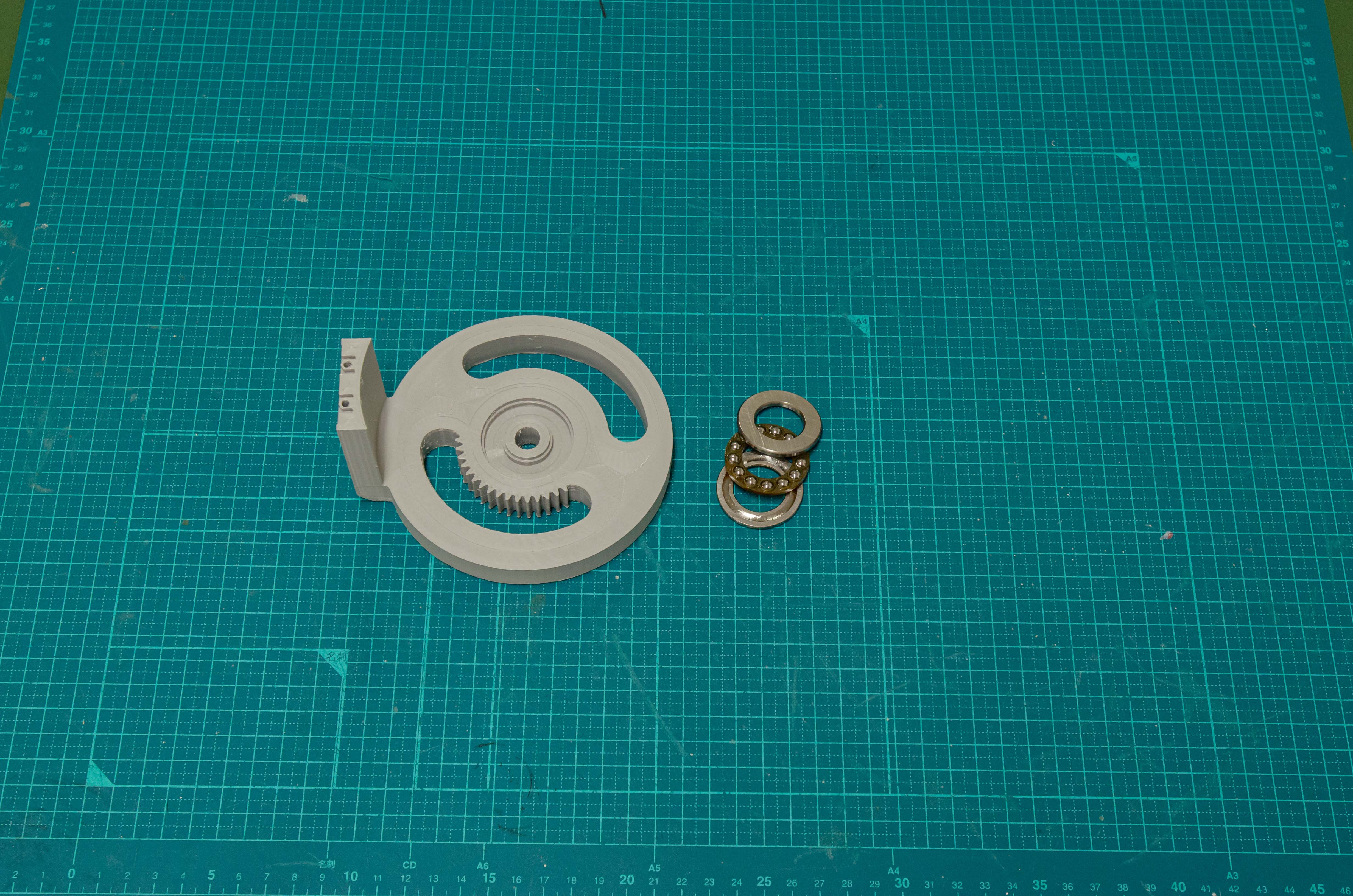
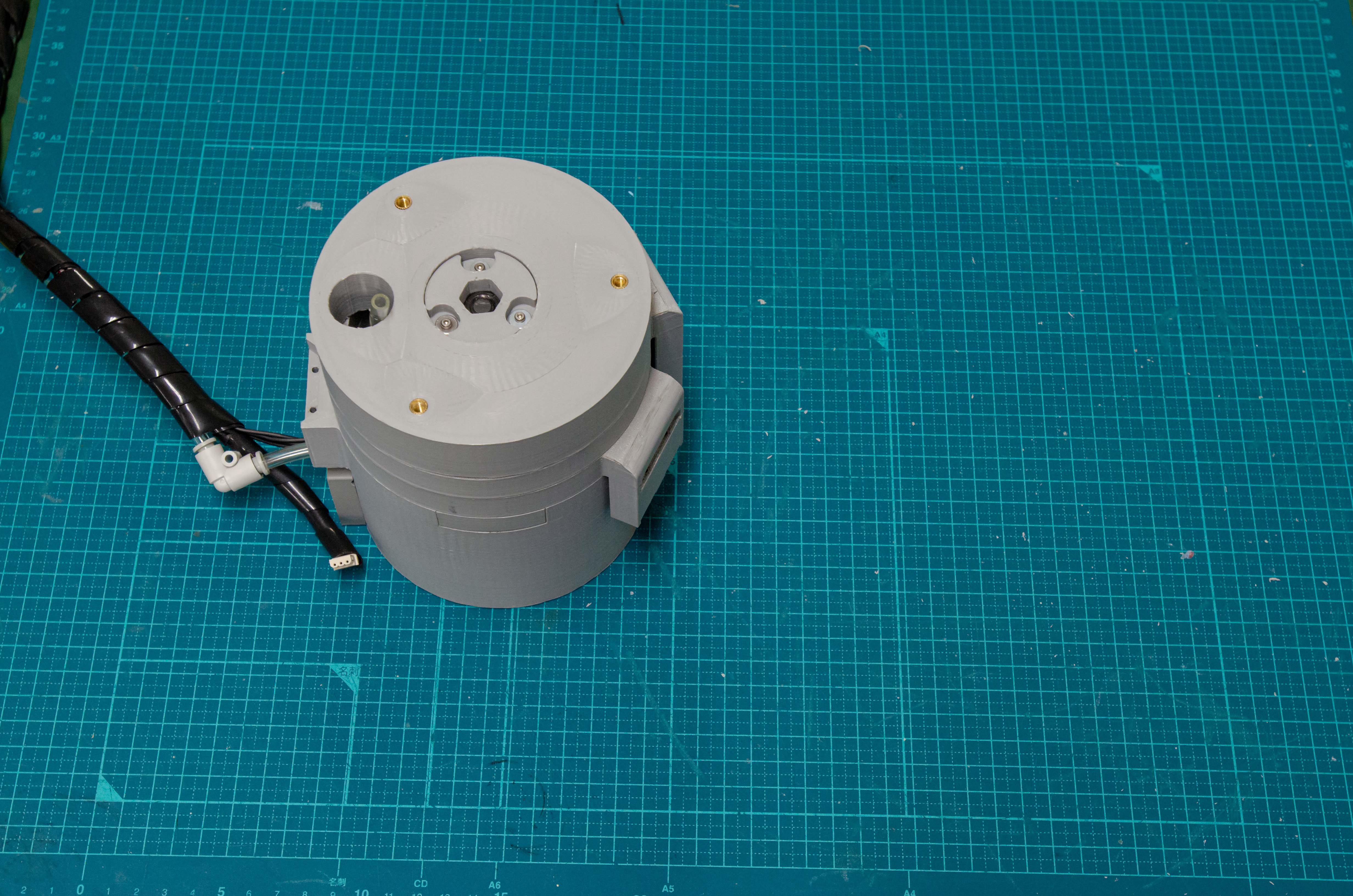
Step 1
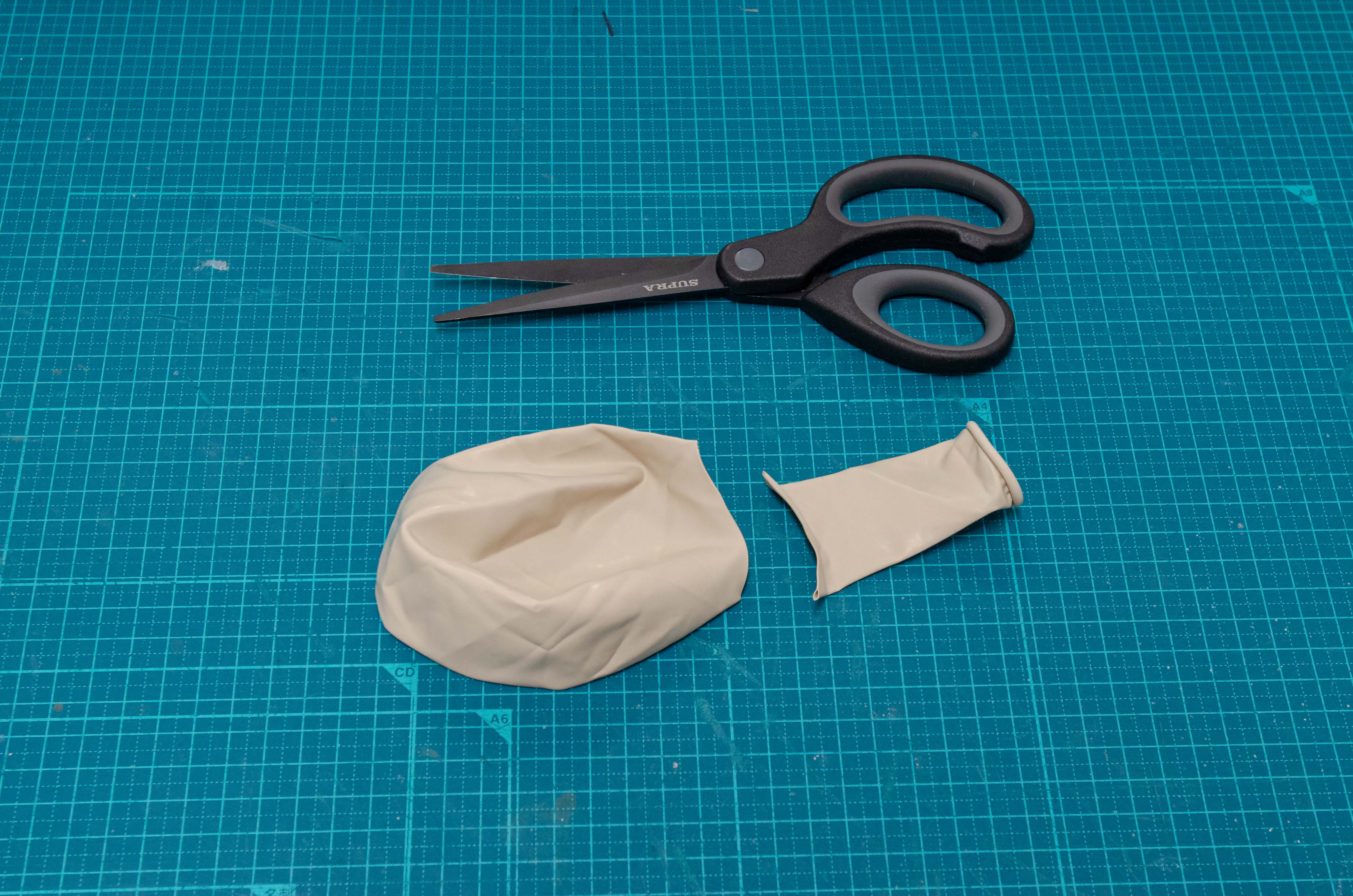
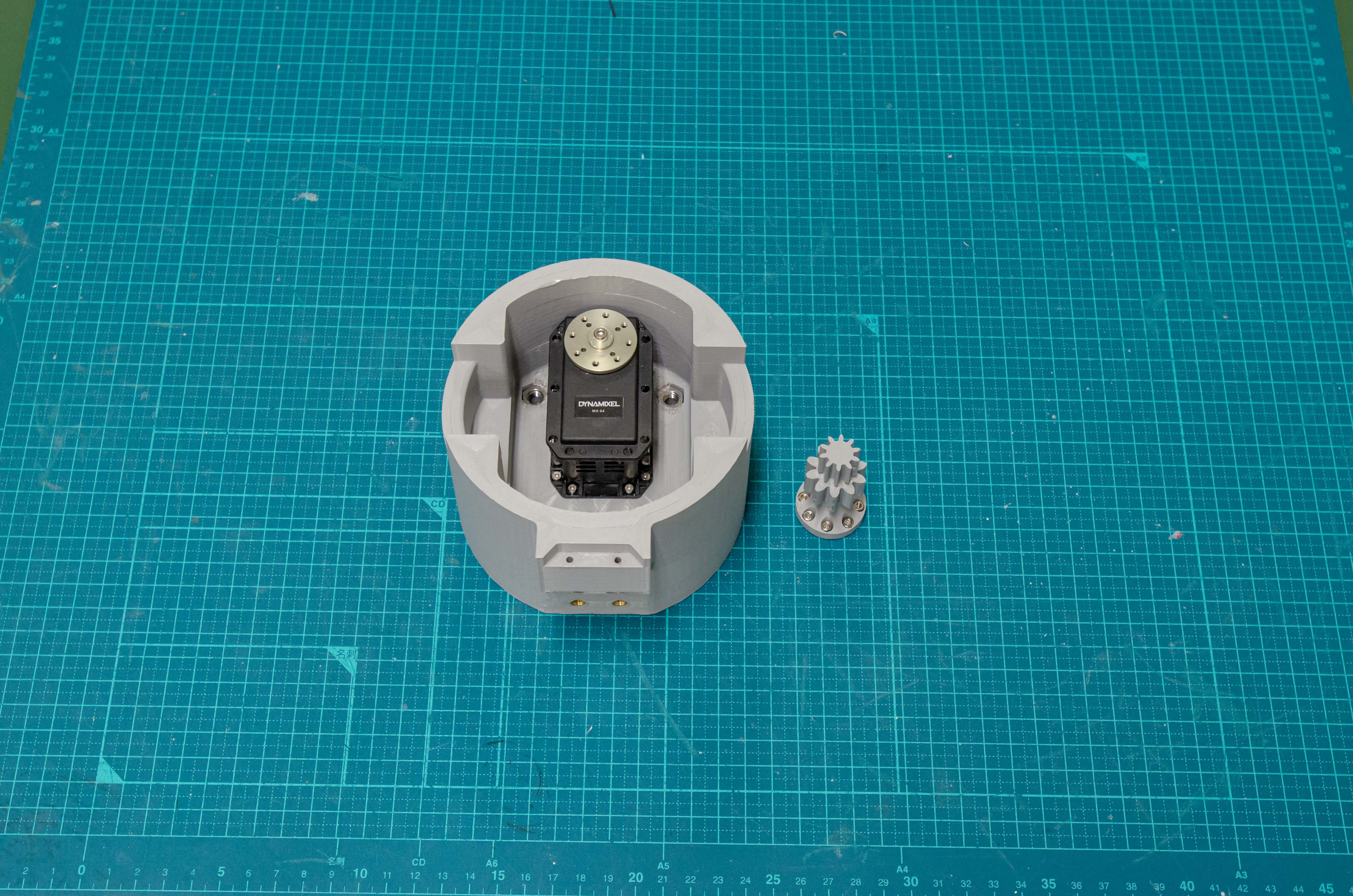
Step 2
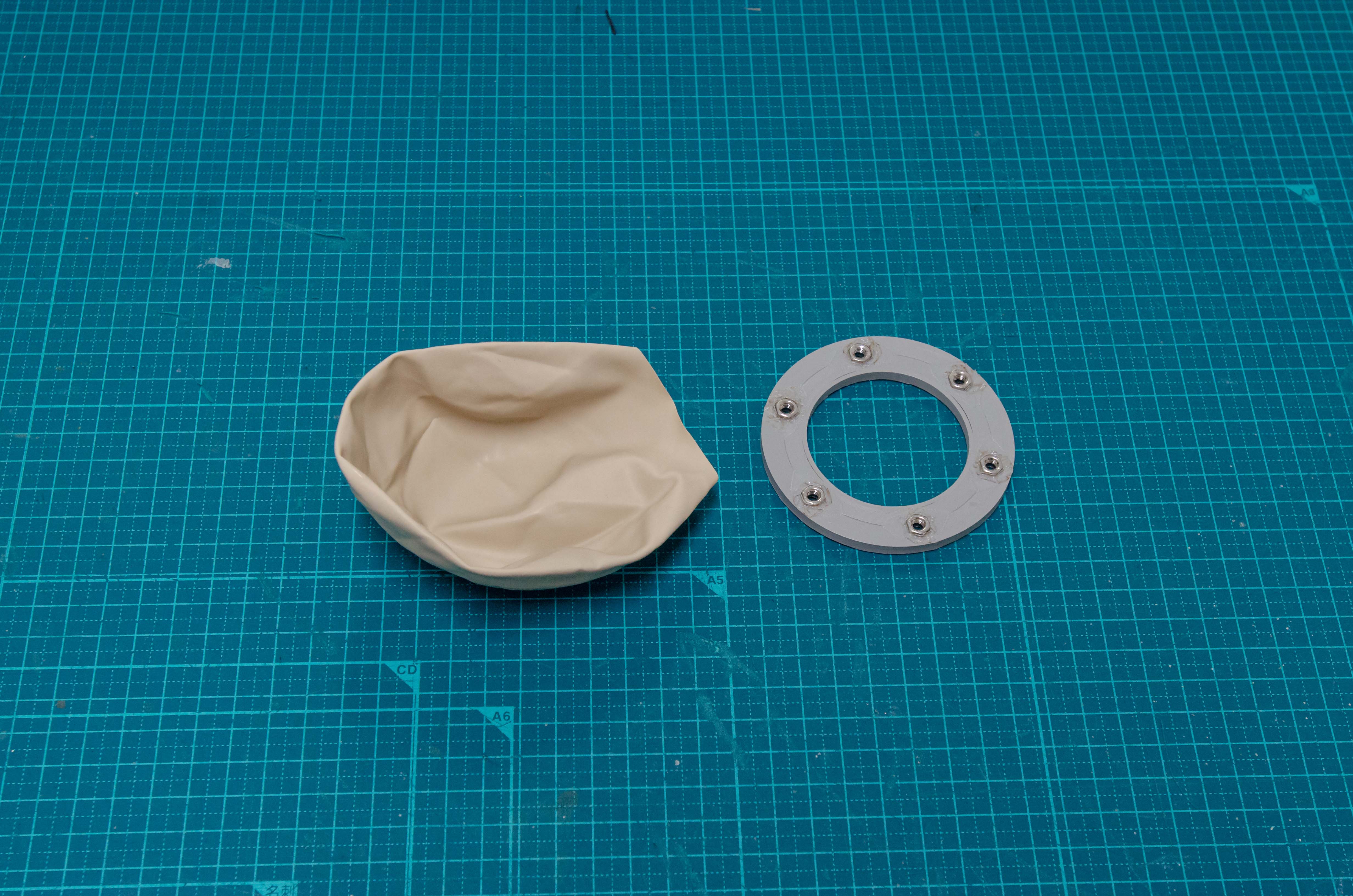
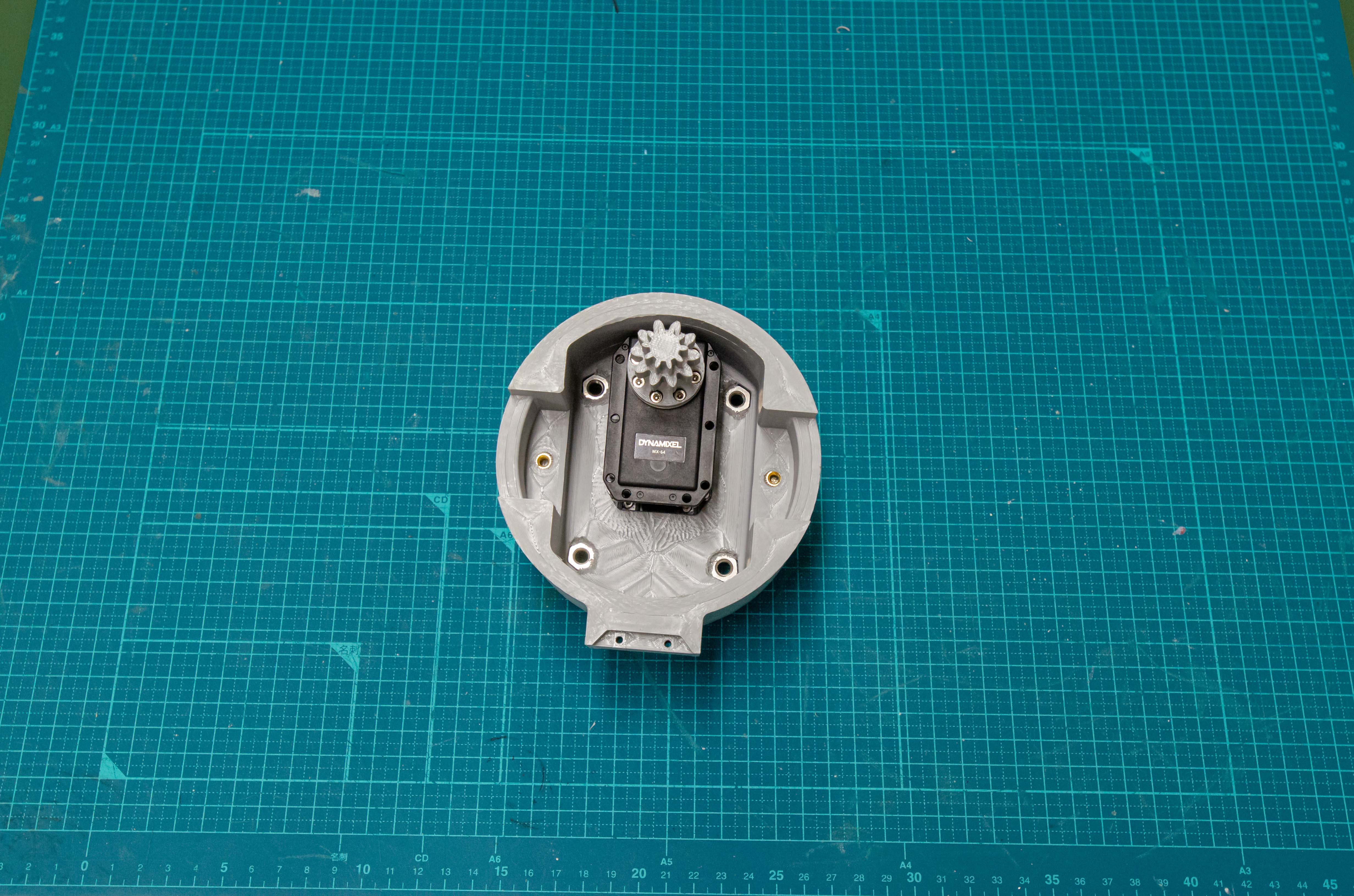
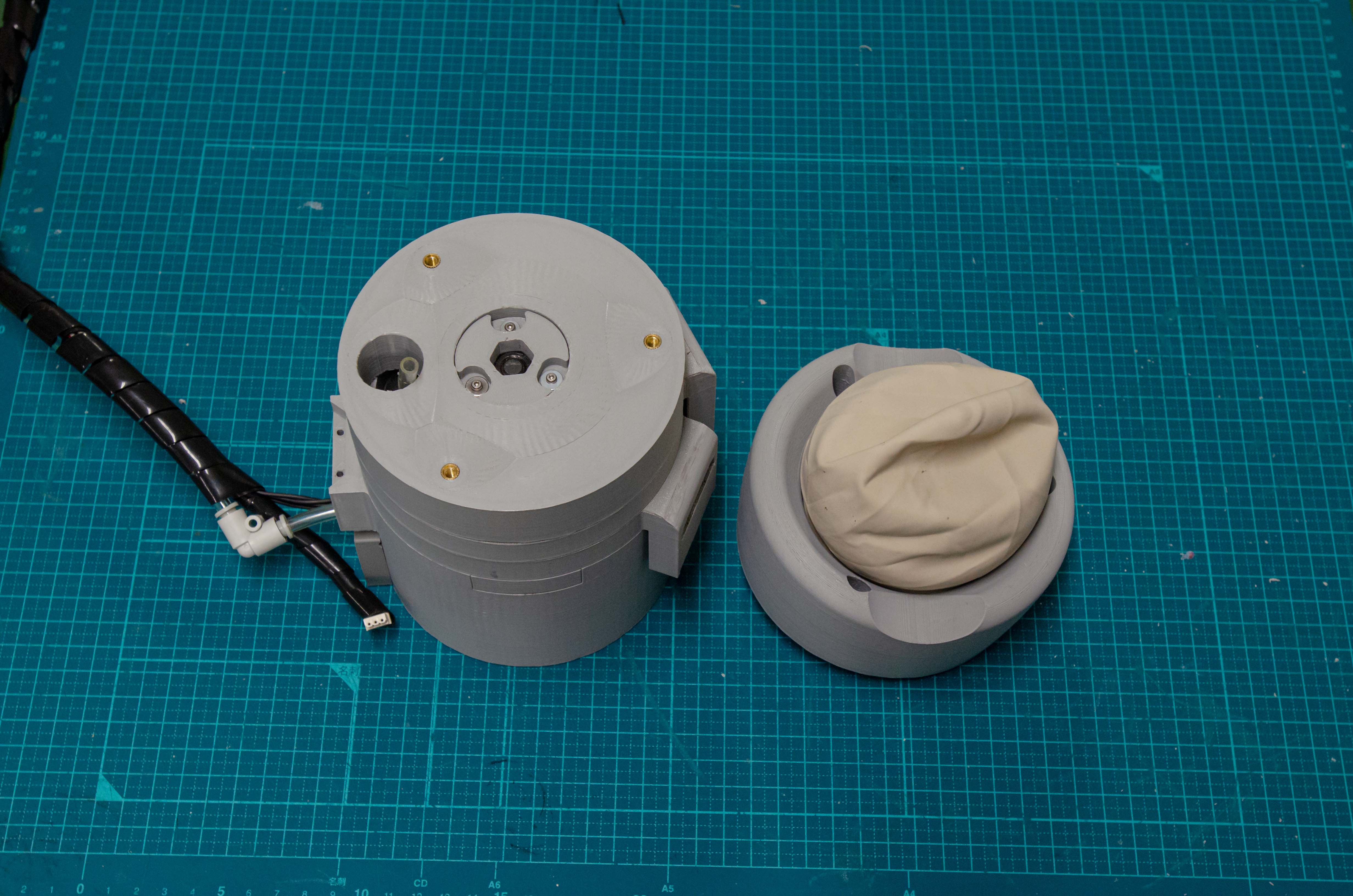
Step 3
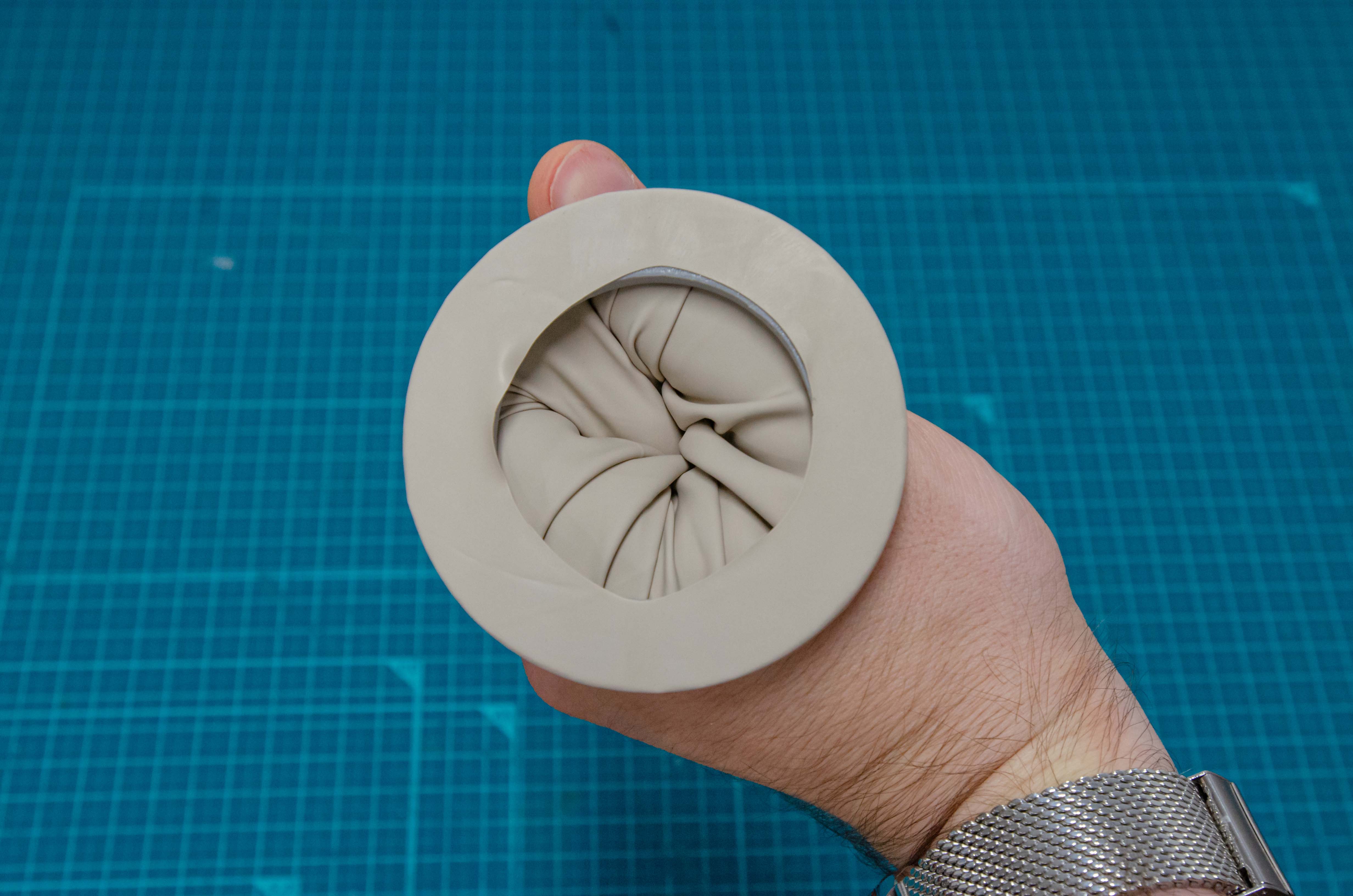
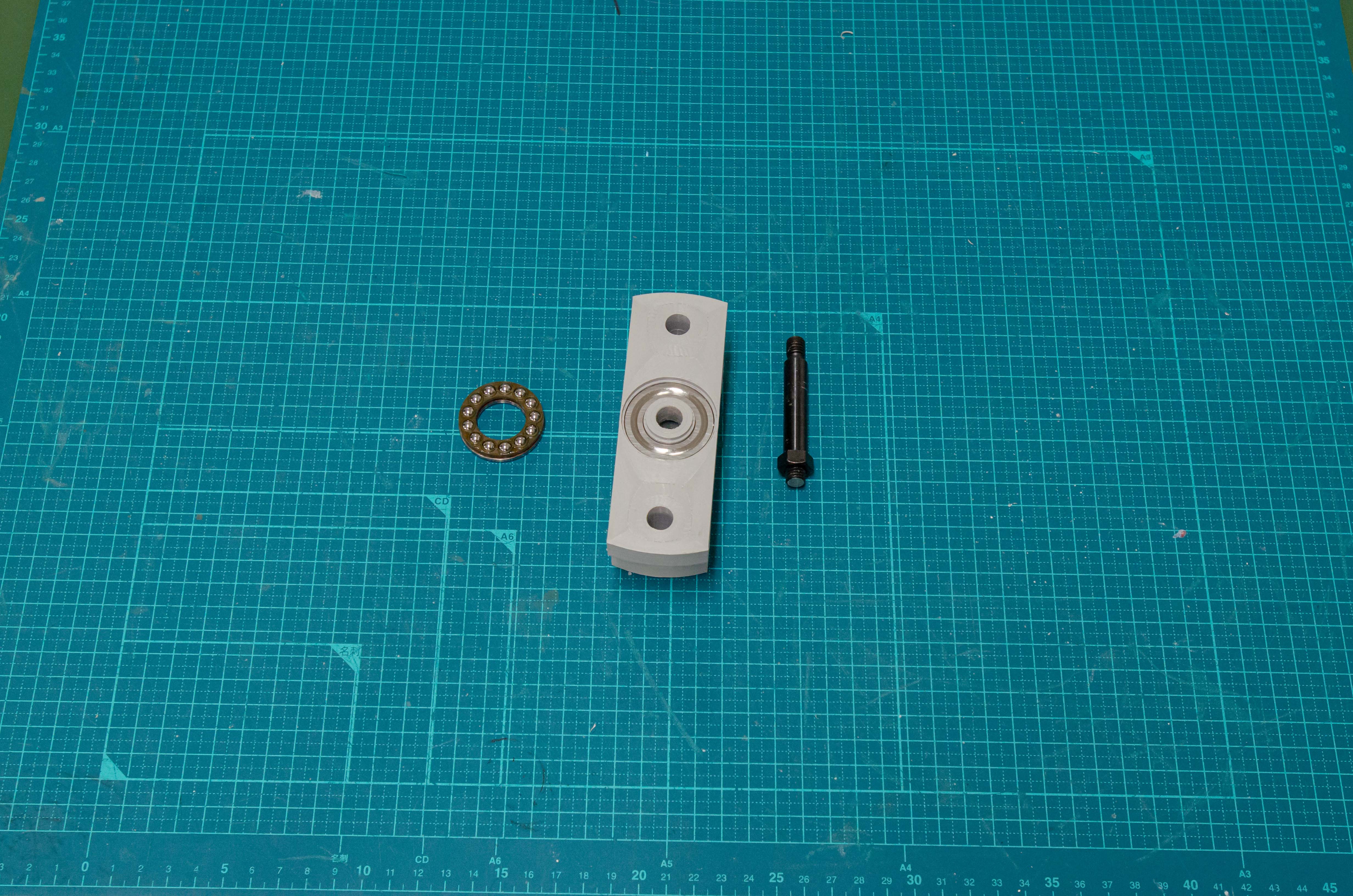
Step 4
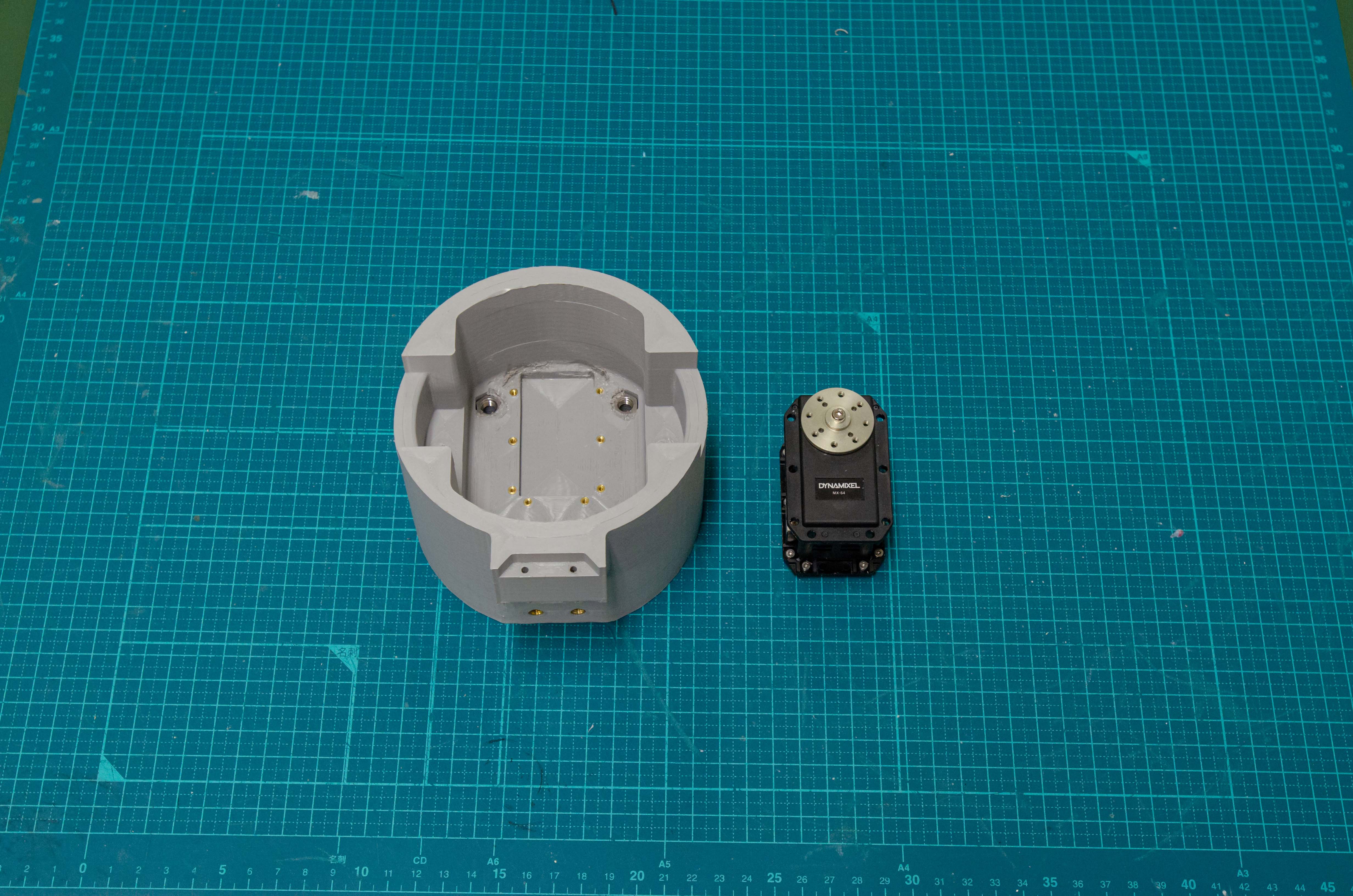
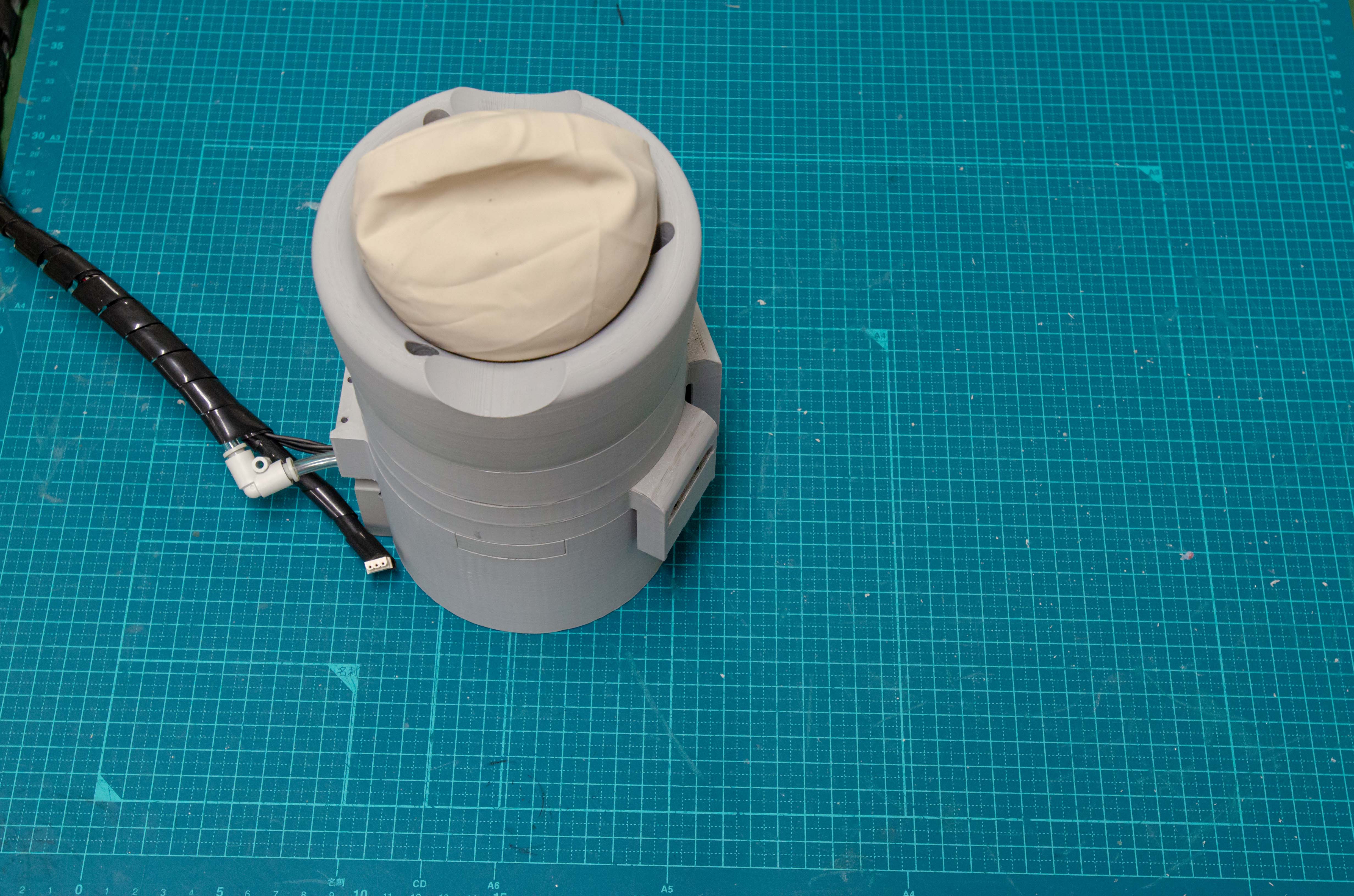
Step 5
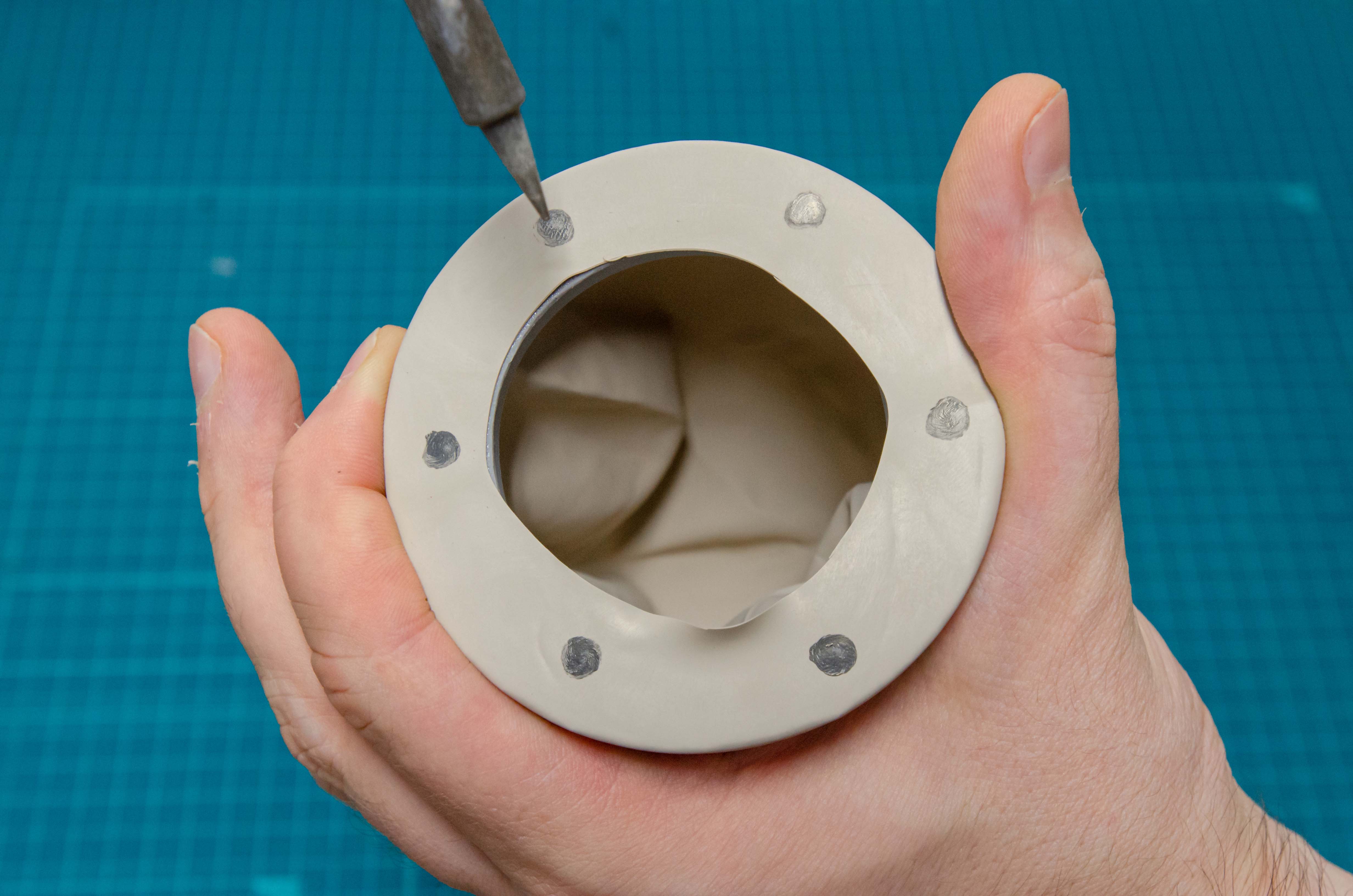
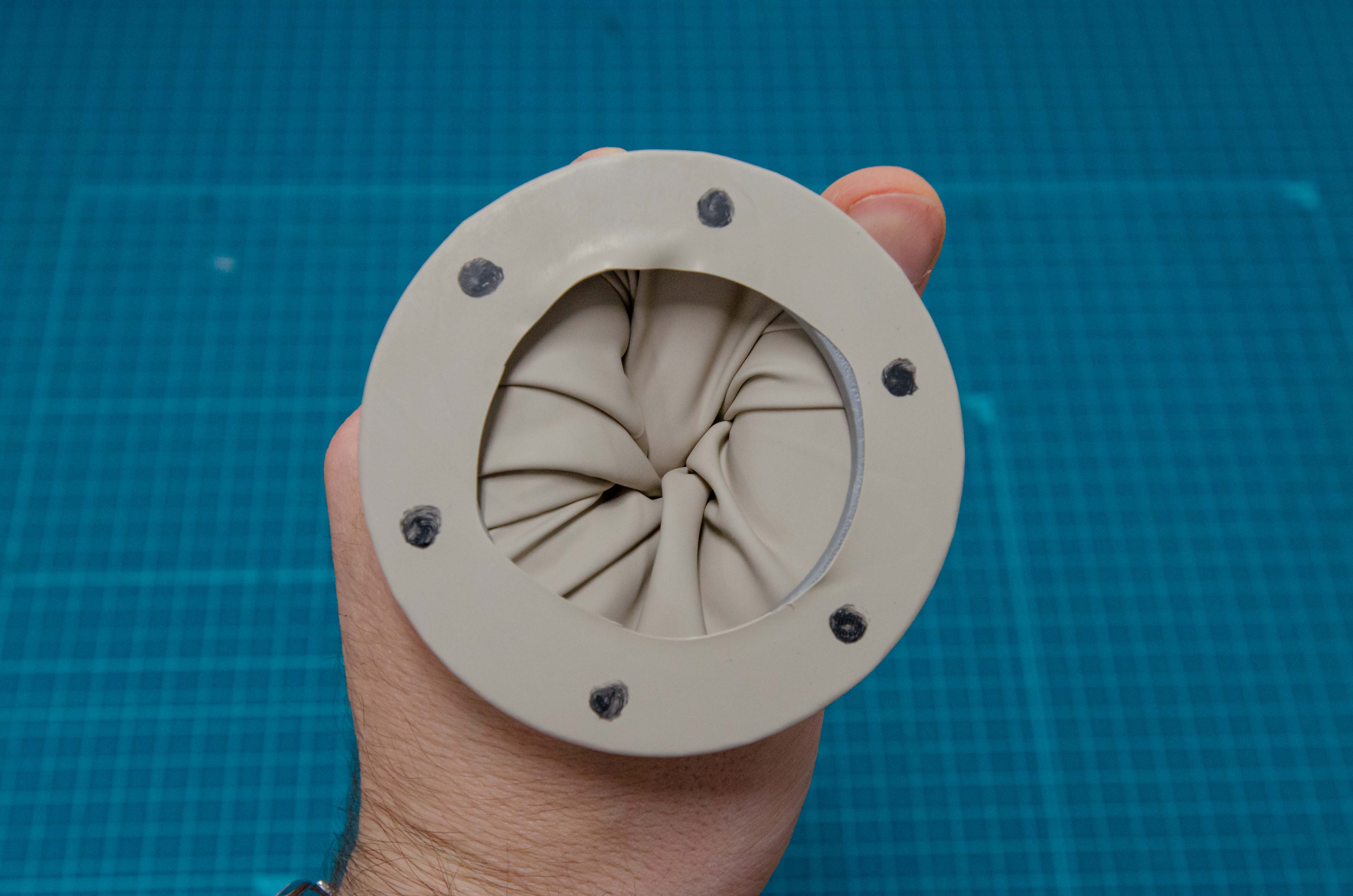
Step 6
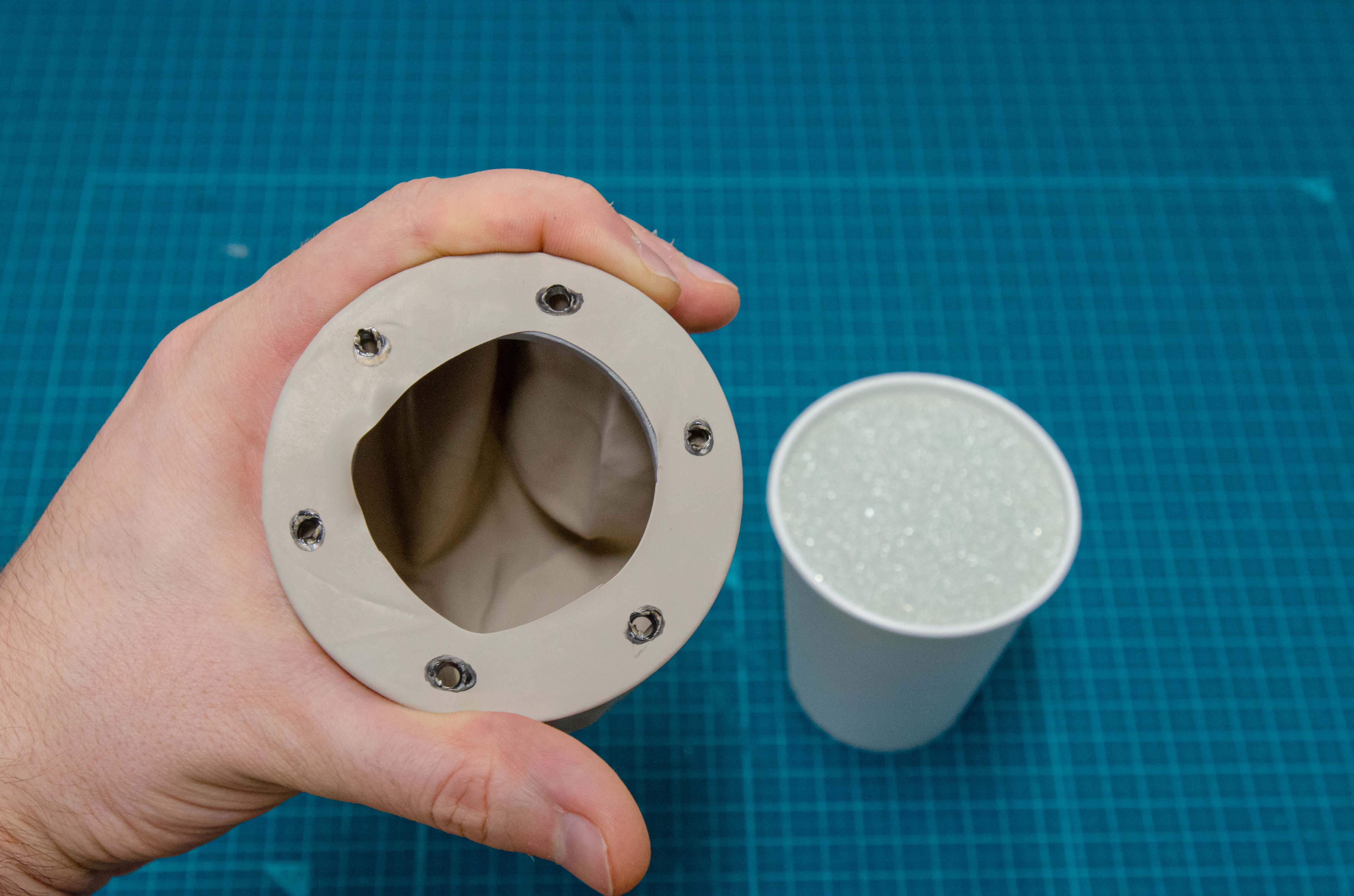
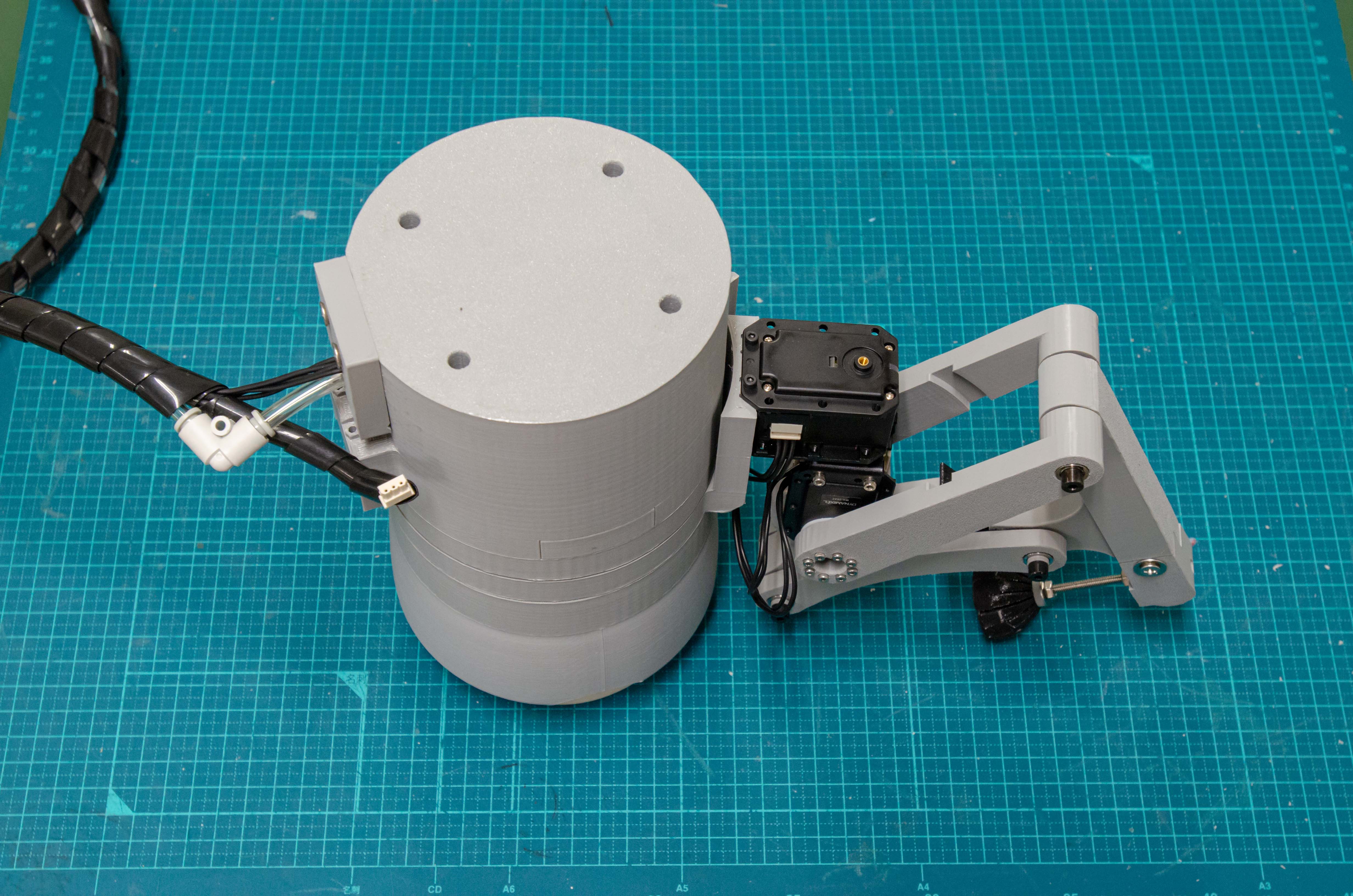
Step 7
Step 8
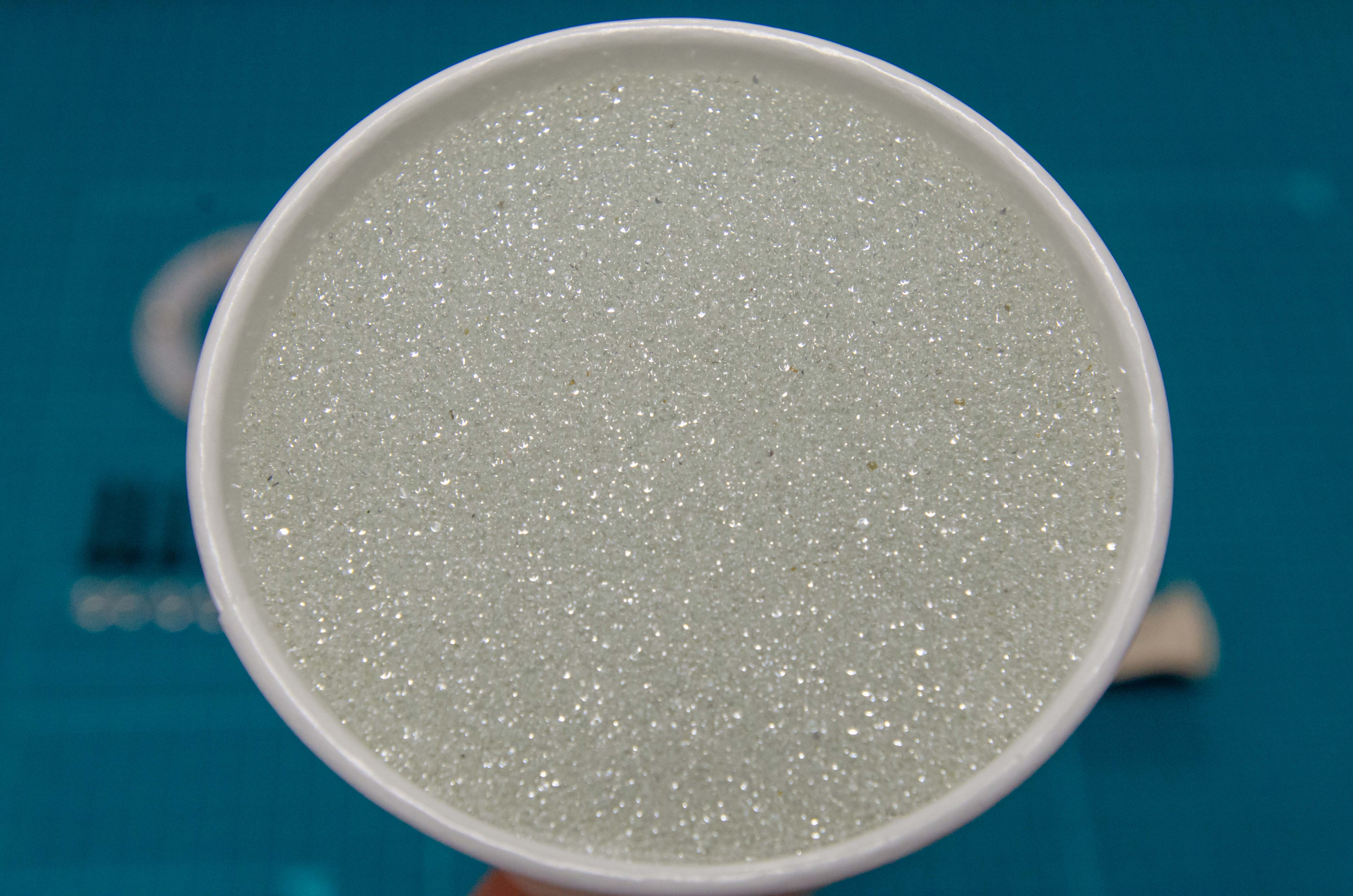
Step 9
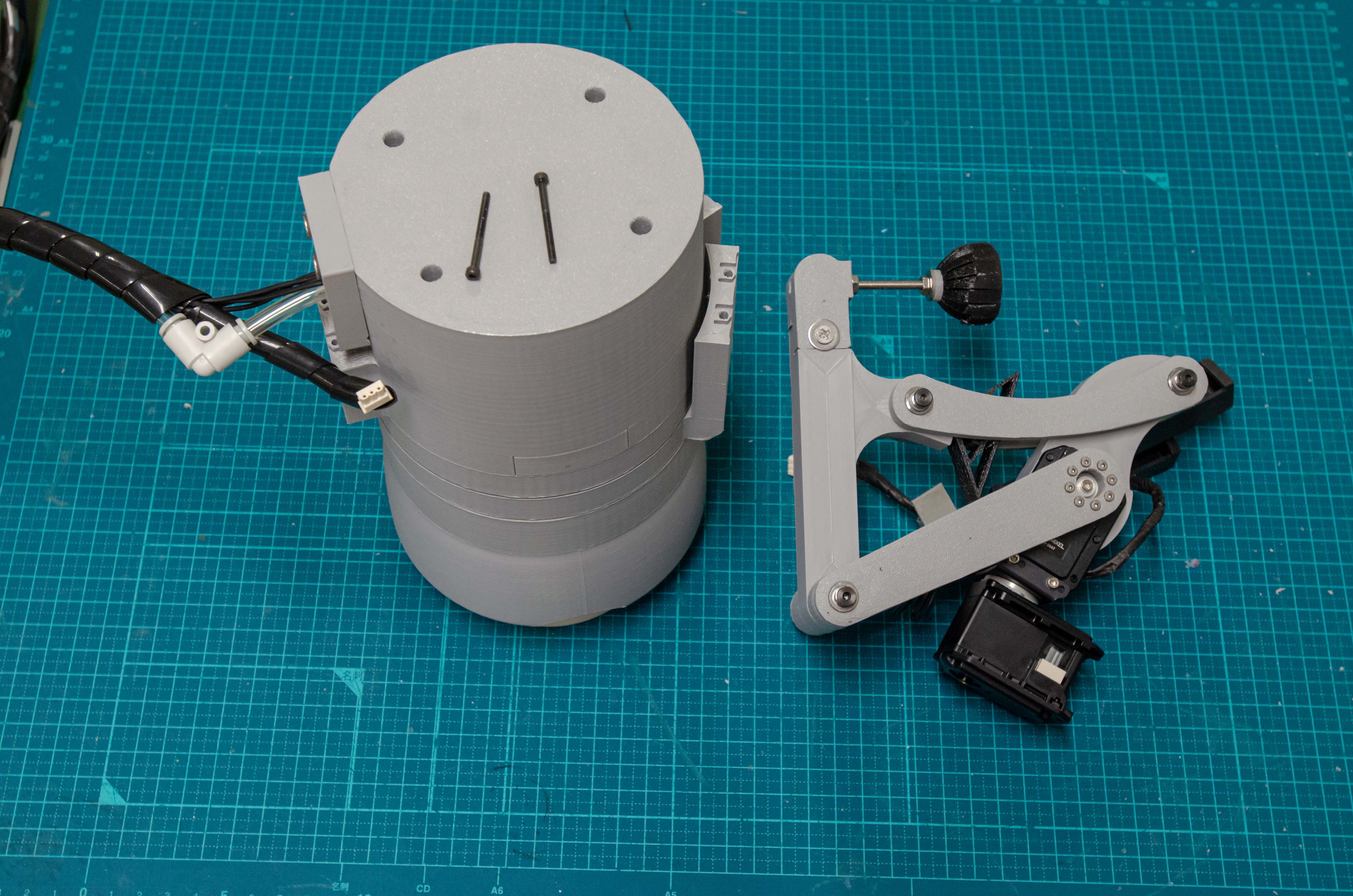
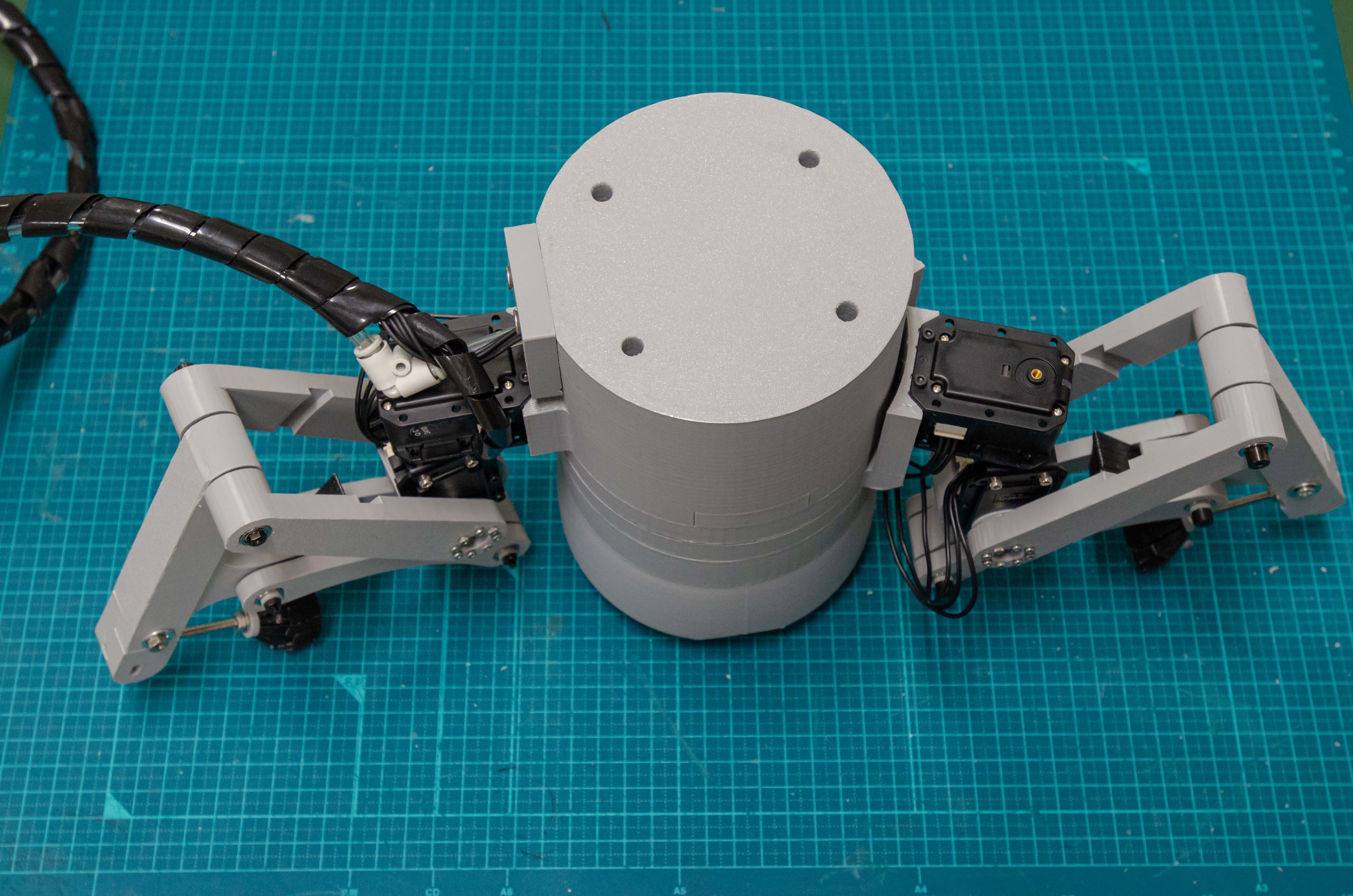
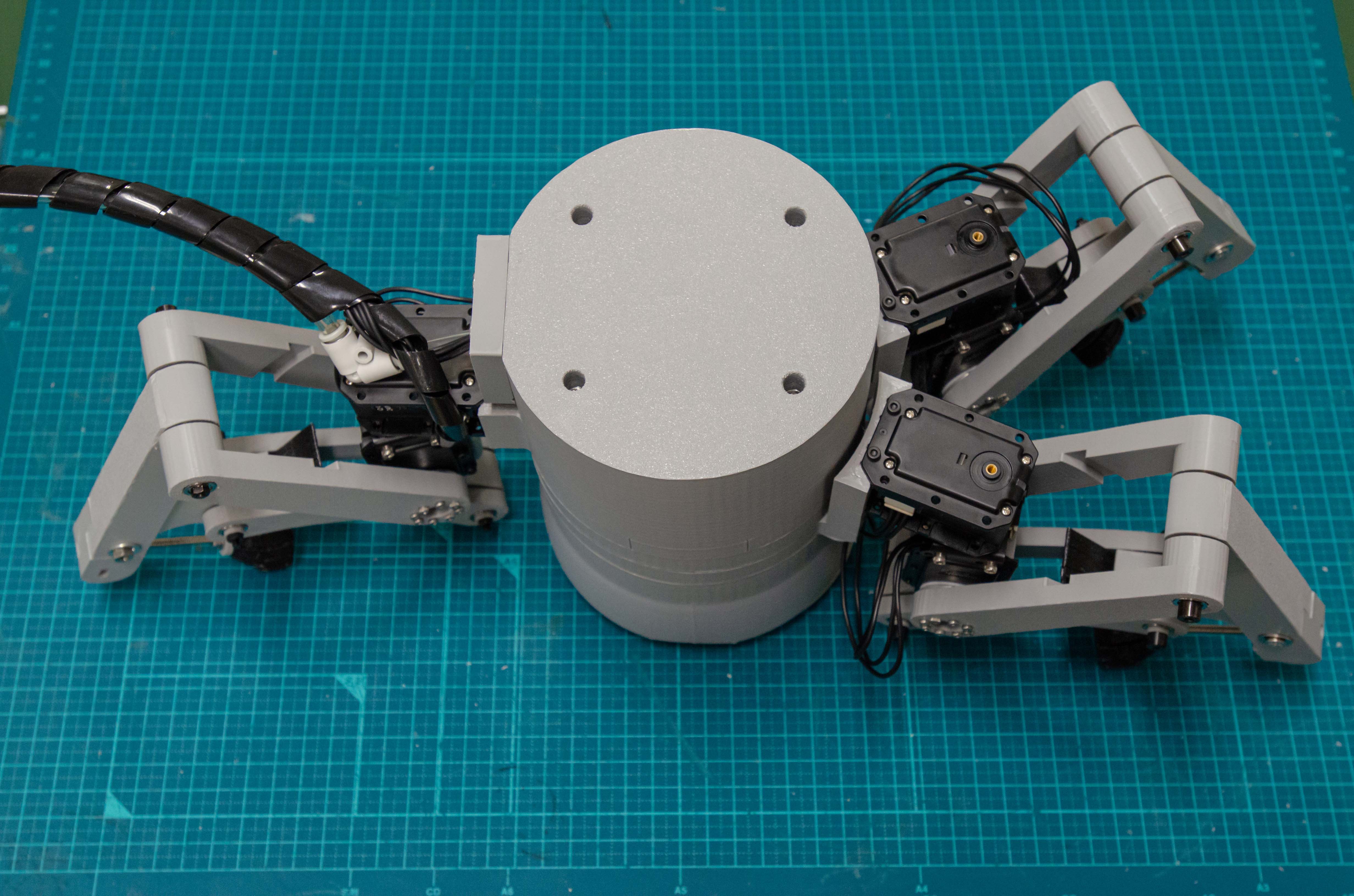
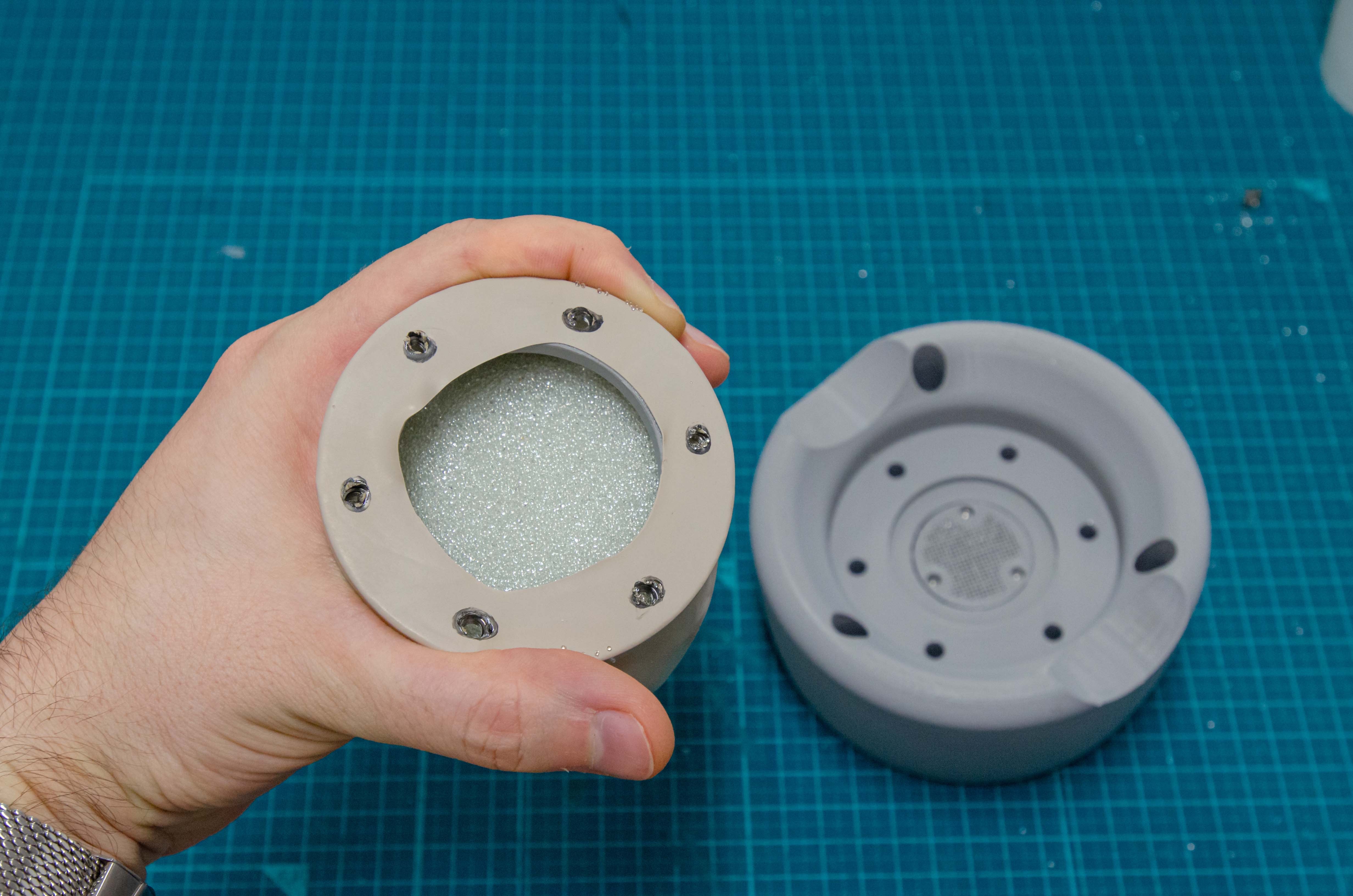
Step 10
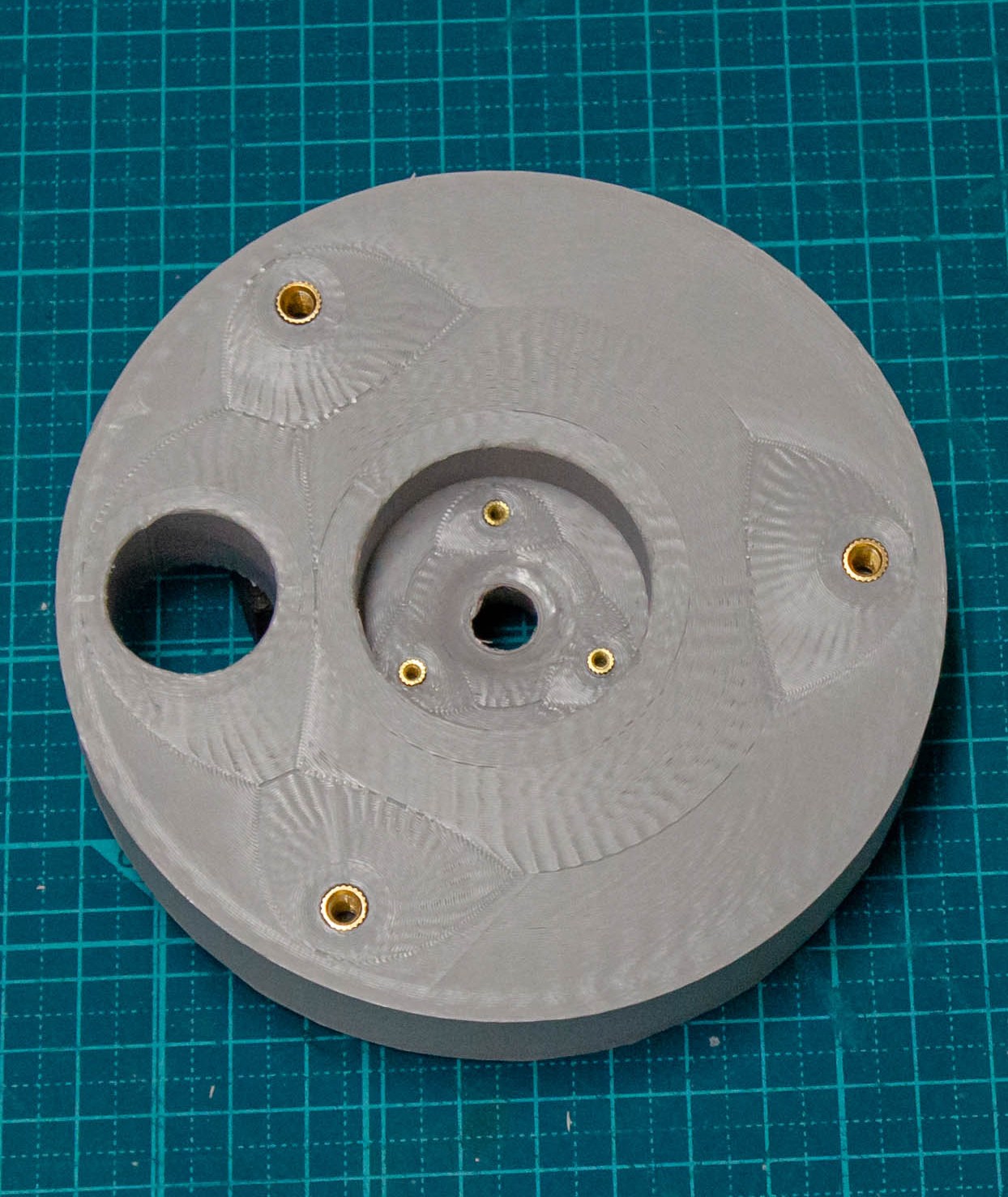
Step 11